Next: 8 Application Experience Up: Appnotes Index Previous:6 Autocoding Tool Evaluations
![]()
![]()
![]()
![]()
Next: 8 Application Experience
Up: Appnotes Index
Previous:6 Autocoding Tool Evaluations

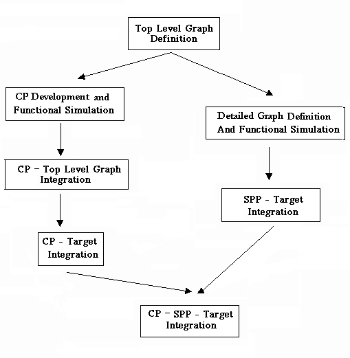
STEP 1: Command Program Development and Functional Simulation
Command Program development starts with overlaying the application mode/submode structure onto the top level graph definition, which enables the execution of AIB. The mode/submode structure of an application will frequently be clearly contained in the application top-level specifications, so after some iteration with the DSP application designer the mode/submode structure can be defined quickly. In fact, it is anticipated that when AIB is incorporated into the DSP application development environment, it will be the responsibility of the DSP application engineer, not the CP engineer, to define the mode/submode structure and to invoke AIB.
Once the Application Specific Interface has been generated by AIB, the construction of the Enhanced Finite State Machine (EFSM) and the User Interface (UI) layers may begin, since either might invoke AIB generated functions. If the EFSM layer is complex, ObjectGEODE (OG) might be used at this stage and if a GUI is required, a GUI builder might also be used to generate the UI. Following construction of the OG model of the CP, it can be exercised using the functional simulator provided by the tool. Since the EFSM layer embodies the heart of the CP application state functionality, this step allows the functionality of the CP to be validated prior to code generation.
STEP 2: Command Program Top Level Graph Integration
Following CP development and functional simulation, the CP is integrated with the top level graph. The Top Level graph at this stage performs only data flow adequate to exercise the command program. Since graphs can easily be retargeted in GEDAE™ this integration can be performed on the CP development host.
STEP 3: Command Program Target Integration
The goal, at this development step, is to verify that the actual command program from the ASI layer up executes as expected with the target hardware and in cooperation with the rest of the command and control system. This is performed independently from the detailed signal processing. The approach is to again use the Top Level graph but to retarget its execution to the final target hardware; this is easy to do in the GEDAE™ development environment. The new launch package will need to be run though AIB, although the ASI layer interface will remain unchanged insuring that higher levels remain untouched.
STEP 4: System Integration
Concurrent with Step 3, Command Program Target Integration, DSP application target integration has been occurring. When this critical step is complete, the final system integration uniting CP and SPP may occur. The experience with the RASSP Benchmark projects showed that this integration step was significantly simplified as a result of the standardization inherent to autocoding technology.
![]()
![]()
![]()
![]()
Next: 8 Application Experience
Up: Appnotes Index
Previous:6 Autocoding Tool Evaluations