Electrical and Computer Enginerring Department
Northeastern University
Boston, Massachusetts 02115
navabi@ece.neu.edu, armita@ece.neu.edu
Simulation time is a crucial bottleneck in the design process. In many cases a simulation is run several times with different inputs. Making such simulation runs parallel will significantly reduce the simulation time. In this paper we are introducing a concurrent simulation implemented with standard VHDL'93 to optimize simulation time of RTL level models.
Since designing at the RT level is more familiar and less time consuming for engineers, optimizing the RT level simulation would optimize the design process. In order to improve simulation speed of RTL descriptions, we have concentrated on methodologies and modeling within a standard VHDL simulation environment, instead of inventing new simulators. One strategy for improving simulation speed is concurrent simulation. In this method a model can simultaneously be simulated with multiple data inputs. This way the overhead of running the simulation several times will be eliminated and the comparison between results will be faster. In addition processing arrays of data can take advantage of concurrent model by moving an entire array or vector of data from or to the memory, between registers, and on buses. By using Shared Variables and Access type the models can expand dynamically with the stream of data coming through them. Every component that receives a list of data at its inputs will process them one by one and produce a list of results at its output. In this paper we will present the VHDL implementation of this concurrent simulation technique.
Section 2 discusses the main concepts of concurrency. In Section 3, we will show how a standard RTL model can be modified to use shared variables for its busses and interconnection lines. Use of variables is the first step in making busses dynamically sizable, and therefore making models accept vectored data. In Section 4 we will discuss the use of Access types for making shared variable busses dynamically sizable. Section 5 discusses the program data format for representation of vectored data. Section 6 conclusions and future work will be discussed.
In general concurrent simulation is when a component model is involved in multiple processing at the same time without having to duplicate every part of the model to accumulate the different processings. Concurrency can be for the same hardware model running different programs, or the same model running same program using different sets of data, or various other configurations. We will use the acronyms SMSPSD (Same Model, Same Program, Same Data), SMSPDD, DMSPSD, etc., for various concurrent simulation configurations. Figure 1 presents a graphical view of a SMSPDD concurrent simulation environment. Where multiple data are to be accessed, a single memory read receives this data. In the structure of the hardware where multiple data reaches the RTL components, these components expand as needed to accumulate the size of the data stack.
The DMSPSD configuration, in which the hardware models are different, corresponds to fault simulation in which different faulty models are running concurrently. At this time we have implemented the SMSPDD concurrent simulation configuration by modeling RTL components in VHDL. This configuration assumes same program flow.
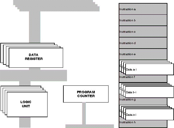
Figure 1. Concurrent Simulation Environment
The use of SMSPDD configuration is in running programs with slight different data sets that would otherwise be running serially one run after another or simultaneously on several machines. One advantage of this concurrent simulation environment is that the results of several runs are accessible for comparisons and analysis in the same machine and in the same processing environment. Another major advantage is in processing loops and arrays of data. Processing of arrays or lists can be done in a burst instead of individually reading and processing data. An operation in a loop receives all the array of data at the same time, performs addition on the individual data and places the data back into the memory all at the same time. Therefore, going through the loop for many times and executing corresponding loop control instructions will be eliminated. Figure 2 illustrates the use of this technique in running loops. The loop in the original code has been replaced with a single add operation. The add operation receives all the data at the same time, performs addition on the individual data and places the data back into the memory all at the same time. In this processing, 150 times going through the loop and executing corresponding loop control instructions will be eliminated.
The implementation of this techniques requires system busses and registers to expand according to the size of data. We have implemented this technique in VHDL taking advantage of dynamic Access types and shared variables of VHDL 93.
Original Code
| Code for Concurrent Simulation |
for (i=0; i<= 150; i++)
{ c(i)=a(i)+b(i); }
| C = A + B |
Figure 2. Concurrent simulation requires one access for a vector
In an standard VHDL RTL model, a bus is the main means of moving data between data components and registers. The bus has a fix width and only one set of data can pass through it at any one time. However, concurrent modeling not only needs multiple data to pass through a bus, but also requires this bus size to be dynamic. To overcome this problem, we have used the VHDL Access type for all the system busses and interconnection lines. In order to have busses visible by all the components that use the bus, we have used shared variables.
The use of variables for busses causes a major problem with timing of events. In a standard RTL description, data from various parts of a circuit are concurrently placed on system busses without any concern for the exact time that the bus data must be available. Events on signals and sensitivity of operations to such events with take care of the timing of events.
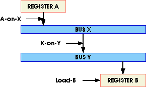
Figure 3. Moving data through busses
For example in a typical RTL description, for moving data from Register A to Register B in Figure 3, Signals for A-on-X and X-on-Y and Load-B simultaneously become active. Since busses are signals, events on carriers closer to source will domino and eventually propagate to the destination. Obviously, we loose this convenience if we replace signals with variables. If all interconnecting lines are variables, movement of data from one place to another must be done in the exact order that the data is to travel. For example in Figure 3, moving data from Register A to Register B can only be done correctly if the control signals A-on-X, X-on-Y and Load-B are activated in this exact order. While changing signals to variables and making them globally available to components of an RTL description is a data path modification, explicit ordering of movement of data through buses requires modification to controller of a model.
From the above discussion, we conclude that dynamic busses are helpful in speeding up the simulation speed by moving multiple sets of data in and out of a VHDL model, but they require modifications both in the data path of a model and its controller. Before a model can become ready for concurrent movement of data, the changes mentioned here must be made to it.
3.1 STANDART RTL
A VHDL RTL model consists of descriptions for the individual components, description for the data unit, the controller, and a description that wires the control and data sections together. The control signals of the components are generated by the controller, and the data signals are attached to system buses in the data section VHDL model. The data unit consists of instantiation of RTL components and assignments to system buses. Control signals used for assignment of values to the buses are generated in the control unit. The control unit generates the control signals for the RTL components through the data unit. A typical state machine description is used for description of this part. The clocking process clocks the new state of the machine and the sequencing process issues control signals based on the current state of the machine. The clock signal used in the controller is also used in all register components. Register load inputs issued by the controller perform their register loading on the edge of this clock signal. This edge also causes transition of the control states.
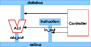
Figure 4. Data and Control in an RTL Description
Figure 4 shows a general diagram of an RTL description. The controller issues signals that control the functionality of ALU and movement of data on busses and in the Instruction Register. In the text that follows, the units shown here will be used as examples of our proposed modeling style for concurrency.
3.2. SHARED VARIABLE BUSSES
This section describes transformation of standard RTL models into modified RTL models with busses that can become expandable for movement of multiple data. The discussions in this section will concentrate on changes in the control section and shared variable busses. Further changes to the structure of buses must be made for making them of Access type and dynamic sizing. Access type shared variable busses will be discussed in Section 4.
3.2.1. Bus Declarations
As previously discussed, all bus and interconnections of an RTL description are replaced by shared variables. A package such as global_environment shown in Figure 5 will contain all bus declarations.
PACKAGE global_environment IS ... SHARED VARIABLE ir_out, ... : byte; SHARED VARIABLE databus : byte; END global_environment; |
ARCHITECTURE structural_rtl OF par_data_path IS . . . SIGNAL ir_out, ... : byte; SIGNAL databus, ... : byte; BEGIN |
Figure 5. Shared Variable and Standard RTL Bus Declarations
Such a package replaces all bus declarations that appear in the data unit of an RTL description. In the shaded area, this figure also shows the replaced bus decelerations from an RTL description.
3.2.2. Register Description
Registers use shared variables for their inputs and outputs. Figure 6 shows RTL description of a register using signals as well as a description that uses shared variables. The shared-variable description will later be modified to be able to handle multiple size data. In this figure, the clock signal is eliminated and the register is only sensitive to the control load input. Since this signal is a toggling signal, a conditional statement for checking the logic level of this signal is also eliminated. In the process statement of the register description, a variable assignment assigns values of the input bus to the output lines of the register.
|
|
Figure 6. Shared Variable and RTL Register Models
3.2.3. Logic units
Logic unit descriptions that use shared variables for their inputs and outputs become sensitive to control inputs as was done for the registers. Figure 7 shows partial code of an example ALU. In this example, input sensitivities are replaced by an alu_opertate control signal. When activated by this signal, the ALU model reads its shared variable inputs, processes the input data, and assign the results to the shared variable outputs.
|
Figure 7. Shared Variable ALU Model
In the shared-variable models, only control signals appear in the port clause, and the data variables have become visible through the use of the global_environment package. The main process statement is sensitive to alu_operate which is a control signal.
3.2.4. Bus Assignments
Bus declarations are all done in a global package for all components to use. As with logic unit and registers, assignments to busses are done to the shared variable representing the bus.
3.2.5. Control Unit description
The key to the correct operation of an RTL description that uses the bus is the way control signals are issued. In the control unit, the basic structure of the state machine remains the same as the original standard RTL description. However, issuing the control signals will be timed instead of becoming concurrently active. Figure 8 shows a control unit description in which the individual control signals are timed for the correct flow of data within data shared variables.
|
Figure 8. Controlling Data Movement by Timed Signals
In this description, all control signal assignments are timed to occur such that they move data from one point in the RTL architecture to another. In step 2 of the controller, mar register is first placed on the adbus. At the same time a read is issued to read data from the memory. A nanosecond later, memory output (dbus), is placed on the databus shared variable. The databus which is the input to the ALU is then operated on by issuing the alu_operate control signal. This is done one nanosecond later than the time that the input to the ALU became available. The shifter which uses the output of the ALU operates another nanosecond later, and at the 5 nanosecond time mark, the load_ir control signal is issued that causes the instruction register to accept its input data.
The previous section discussed the use of shared variables for system busses and the influence of such a change on the control unit. Because the busses are variables, they can become of Access type, allowing them to be dynamically sized. This change will influence the way RTL components are modeled, but, assuming SMSPDD parallelism, this will not influence the control unit. The signals from the controller should still be ordered according to the flow of data as in the shared variable models. However, parallelism in the movement of data will require a different control program to be executed. This control program has the same flow as the original control program, but allows movement of burst data into the processor model..
4.1. Dynamic Bus Declaration
To implement the dynamic nature of interconnections in a simulation environment , link lists are used. This implies that system busses should be declared as ACCESS types. So that such bus will be a pointer to a link list that carries the data. Link lists will expand to match the size of data that is to be processed simultaneously. Figure 9 shows the type declaration need for this purpose. The examples shown is to replace the byte type of the previous section. This type which will be used as a node in the list has a data part and a link part. Data part will carry the data to be processed and link part will point to next in the list.
|
Figure 9. Dynamic type declarations
|
Figure 10. System buses and register outputs
Using the above type declarations, system buses should now be declared as shown in Figure 10. This declarations is very similar to that of Figure 8. The only difference is the use of Access types for the busses.
|
Figure 11. Concurrent model of a simple register
4.2. Dynamic Register Declaration
Registers have Access type shared variables for their inputs and outputs. Each time a register is loaded, it makes a copy of its input list and makes its output point to this new list. To avoid running out of memory space, first the previous list that the output was pointing. to will be freed and then new memory will be allocated. This way, the output will be dynamic and the same size as the input. Figure 11 shows an example of a register used for concurrent simulation. As it can be seen, the register is still sensitive only to its load input.
4.3. Dynamic Logic Units
As with the registers, dynamic logic units are sensitive only to their control signals. Logic unit inputs and outputs are buses declared as shared variable pointers. When a logic unit is activated by a control signal that it is sensitive to, it will start processing its input link lists. For a set of data, a single activation from the control units causes burst of data to be processed by the logic unit. Other control signals will specify the operation to be done on the inputs. Logic unit will loop and repeat the specific operation on all the elements of the inputs and places the results in a link list. When done, the output will be made to point to the result link list. An example ALU model illustrating this technique is shown in Figure 12 .
|
Figure 12. ALU example
4.4. Dynamic Bus Assignments
Bus assignments remain the same as those of non-dynamic shared variables. The difference is in the type of the busses. In the dynamic bus models, input and output variables are Access type shared variables. Assignment of the input of a dynamic bus model to its output is done by setting the bus output pointer to that of the input. This way, the same memory will be used for the input and output and no allocation and deallocation is done.
11100001 11101000 00010000 00100111 --cla --asl --lda,i p1 --39 01010000 00101000 10110000 00101001 --add,i p2 --40 --sta,i p3 --41 11100001 11101000 00000000 00100111 --cla --asl --lda p1 --39 01000000 00101010 11100001 11101000 --add #0 --42 --cla --asl 00000000 00101000 01000000 00101010 --lda p2 --40 --add #0 --42 11100001 11101000 00000000 00101001 --cla --asl --lda p3 --41 01000000 00101010 11100001 11101000 --add #0 --42 --cla --asl 00000000 00101011 01100000 00101100 --lda count --43 --sub #1 --44 11110010 00100110 10100000 00101011 --bra_z end --38 --sta count --43 10000000 00000000 11101111 00101101 --jmp --00 --halt --p1 00101110 00101111 00000000 11111111 --p2 --p3 --#0 --count=255 00000001 00000001 00000010 00000000 --#1 --data --data --data 00000000 |
4.5. Dynamic Memory Model
Expansion of data begins from the memory. When a set of data is addressed in the memory, all the bulk data, which we will refer to as a vector of data will be expanded by making the memory data bus point of the word in the memory where the vector data is stored. Vector data in the memory appear as binary data separated by colon. The model for the memory reads an input file of binary data is the format shown in Figure 13a. Each line of the file is one word of the memory. Memory model reads each line and checks to see if a colon follows the data binary value. If so, the word is a vector data. Memory is also written in a way that each word is stored in a link after it is read from the file. When a word of memory is addressed by the processor it will make a copy of the link list stored in that location of memory and the memory expanded bus will be pointing to this link list.
Figure 13 show a program written in an example assembly language. This program adds 256 numbers and places the result in another array. The code in Figure 13a loops 256 times and each time it reads bytes from the memory and places each resulting data back into the memory. Figure 13b uses expanded data and performs only two reads for reading the two vector operands, and one write for writing the results. Simulation time for running the code of Figure 13b is two order of magnitudes faster than that of Figure 13a.
This work on the concurrent models has shown that significant performance improvement can be obtained by modeling hardware to move bulk of data. We have completed models for concurrent registers, memory, and several logic units. Work in this area should concentrate on formulation of transformation of standard RTL models into concurrent models, generation of models for other RTL constructs, development of compilers with vectored data for the concurrent memory model, and development of transformation programs. Work on other concurrency schemes should also be considered.
- CONCURRENT SIMULATION
- [1] E. Ulrich, V. Agrawal, and J. Arabian, "Concurrent and Comparative Discrete Event driven Simulation," Kluwer Academic Publishers 1994.
- [2] S. Gai, P. Montessoro and F. Somenzi, "MOZART: A Concurrent Multilevel Simulator," IEEE Trans. on CAD , vol. 7, No. 9, September 1988.
- [3] P. Jain and G. Gopalakrishnan, "Efficient Symbolic Simulation-Based Verification Using the Parametric Form of Boolean Expressions," IEEE Trans. on CAD , vol. 13, No. 8, August 1994.
- [4] C. Hansen, "Hardware Logic Simulation by Compilation," DAC 1988.
- [5] T. Sasaki et. al, "HAL; A Block Level Hardware Logic Simulator," DAC 1983
- [6] M. Heydemann and D. Dure, "The Logic Automation Approach to Accurate and Efficient Gate and Functional Level Simulation," IEEE Trans. on CAD 1988.
- [7] Z. Wang and P. Maurer, "LECSIM: A Levelized Event Driven Compiled Logic Simulator," DAC 1990
- [8] E. Ulrich, "Table Lookup Techniques for Fast and Flexible Digital Logic Simulation," IEEE Trans. on CAD 1980.
- [9] R. Bryant, "Symbolic Simulation-Techniques and Applications," DAC 1990.
- [1] E. Ulrich, V. Agrawal, and J. Arabian, "Concurrent and Comparative Discrete Event driven Simulation," Kluwer Academic Publishers 1994.